|
|
|
 |
The DES core is a sequential-hardware implementation of the DES
algorithm. Each of the 16 rounds involved in encrypting/decrypting a
64-bit data block is implemented by making use of a single, reusable
hardware resource module. This module is designed as a generic unit so
that it can accommodate all the variations specific to each of the 16
rounds. Sub-keys generation is also handled inside the core.
The DES core is designed to work together with a CBC
Shell and a bi-directional serial
interface (as optional interfaces).
Performance
A typical 0.35u/3.3V technology implementation runs at around 200MHz,
delivering a 0.8 Gbps peak performance.
The core's gate-count is around 3500 gates.
Interface Signals

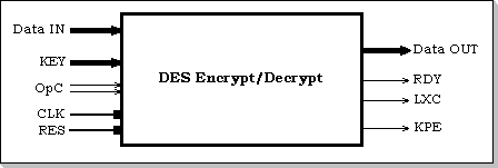
Figure 1: DES Core I/Os
The DES core is processing data that is input via the Data-IN port, and
is delivering the result via the Data-OUT port. A separate KEY port is
used for providing the core with the encryption/decryption key.
Apart from these three main busses, the following handshaking/control
lines are provided (fig. 1):
OpC: The OpCode specification. This is a 2-bit input by which
the core is instructed what to do starting after the current operation
is completed. It can have the following legal values: NOP - no
operation; ENC - next input data is to be encrypted; DEC - next input
data is to be decrypted.
RDY: This is an output status line active when the core is
idling (is executing NOPs).
LXC: This is an output status line active during the last cycle
of any core operation except NOP (i.e. during encryption and decryption
operations).
KPE: This is the key parity error signal; it is an asynchronous
output.
CLK: The core's internal clock; all the core operation (except
reset) is synchronous w/r to this clock signal.
RES: The core reset; this is an asynchronous global reset
signal.
Core Functionality
When internally "ready", the DES core can initiate one of the following
three operations at the beginning of the next clock cycle:
NOP - during a NOP the core is idling; a NOP operation
takes 1 CLK cycle.
ENC - during an ENC data is encrypted according to the
key; an ENC operation takes 16 CLK cycles.
DEC - during a DEC data is decrypted according to the
key; a DEC operation takes 16 CLK cycles.
Timing
The core is sampling the OpCode bits only in those cycles when either
RDY or LXC are asserted (on the rising edge of the CLK); in the rest of
the clock cycles (when the core is processing a data block) the OpCode
bits are ignored (they are not sampled).
Both the key and the input data are loaded simultaneously (from the KEY
and respectively the Data-IN inputs) into the core at the beginning of
any encryption or decryption operation (on the CLK rising edge).
The processed data is valid at the Data-OUT port at the end of the last
cycle of an encryption/decryption operation; the CLK rising edge can
thus be used to strobe the result during the cycle when LXC is asserted.
Depending on how the RDY and LXC signals are interpreted, three modes
of operation result: block mode, streaming mode, and mixed mode. These
three modes only reflect different ways of interfacing the core; they
are not actually distinct internal core operation modes.

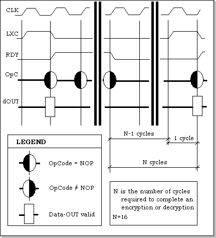
Figure 2: Block mode of operation
The block mode of operation results from only considering the RDY signal in order to determine the internal state of the core: the core is assumed to be internally "ready" when RDY is asserted. Initiating a new ENC/DEC operation will thus be allowed when the RDY signal is asserted. However, since the RDY is only asserted after the total completion of an operation, there will be (at least) one NOP intercalated between any two other operations (fig. 2).

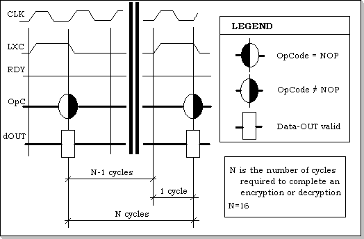
Figure 3: Stream mode of operation
The stream mode of operation results from only considering the LXC signal in order to determine the internal state of the core: the core is assumed to be internally "ready" when LXC is asserted. A new ENC/DEC operation will thus be initiated whenever the LXC signal is asserted, i.e. in the very next cycle following the last cycle of the previous operation. This mode will have no NOPs intercalated between the other operations (fig. 3).
The mixed mode directly results from mixing the block mode with the stream mode. In this mode the data blocks are supplied as a stream to the DES core, but the stream can be broken at any time with NOPs.
The RDY and LXC signals can be OR-ed together to provide a new DRQ (data request) flag signal. This signal being asserted will mean that the core is ready to accept a new data block to be processed according to the specified key. A core feeding scheme can be designed around the composite DRQ signal, instead of the separate RDY and LXC signals.
The KPE signal is an asynchronous signal asserted whenever a key parity error is detected on the key port and the current OpCode specification is either ENC or DEC. If the OpCode is neither ENC nor DEC, the key's bit configuration is not checked and key parity errors are not reported.
Final Remarks:
- KPE is an asynchronous output; it is not internally related in any way with the core's CLK.
- RES is an asynchronous signal; it should be released at least half a cycle before CLK's rising edge.
- A half-cycle setup time is a covering value for all inputs.
- Output data must be sampled using the CLK signal's rising edge; it is only valid on the leading rising edge of the clock cycle starting after a last instruction cycle; output data is not internally latched.