|
|
|
 |
The BCSI is a bi-directional interface designed to connect a frame-based serial data stream to a block cipher operating in CBC mode. Because the input data is processed in blocks by the cipher, a number of restrictions are imposed on the input data stream timing; the output data stream timing is guaranteed (by the BCSI design) to obey these restrictions, thus allowing bi-directional and/or chained operations of BCSI modules.
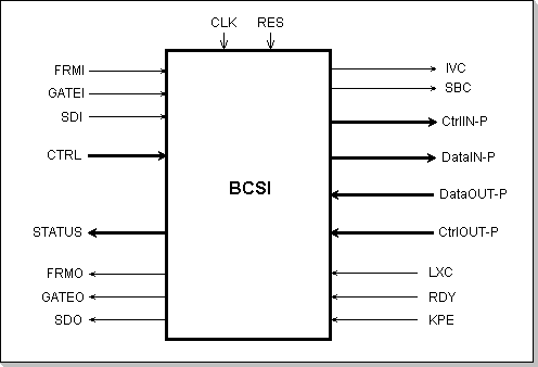
Figure 1: BCSI Signals
Signal Description
The BCSI interface signals can be grouped in two categories: the Control and Serial Communication signals, and the Block Cipher Interface signals (depicted on the left and respectively on the right in Fig. 1).
CLK - The BCSI Clock. The internal BCSI operation is synchronized by
this clock.
RES - The BCSI Reset. This is an asynchronous signal.
FRMI - Frame Input. This signal is validating a data frame; it has to
be enabled at the beginning of a frame and has to be disabled at the
ending of a frame. Some restrictions are imposed to the delay between
two consecutive frames in order to allow enough time for the data to be
processed by the block cipher.
GATEI - Gate In. This signal is validating the input data, on a per-bit
basis. Some restrictions apply to the relative timing of this signal
with respect to FRMI.
SDI - Serial Data In. This is the serial-data input stream. Each input
data bit is strobbed on the rising edge of the CLK signal, if both the
GATEI and FRMI signals are active.
FRMO - Frame Output. This signal is generated by the BCSI; it has the
same meaning as the FRMI, but applies to the output serial data stream
generated by the BCSI. It is guaranteed to obey the timing restrictions
of FRMI, thus allowing chaining of BCSI modules.
GATEO - Gate Out. This signal is generated by the BCSI. It is not a
(delayed) replica of the GATEI input, but it is guaranteed to obey the
GATEI timing restrictions, thus allowing chaining of BCSI modules.
SDO - Serial Data Out. This is the serial-data output stream.
CTRL - This is the BCSI parallel control port; it contains a number of
parallel busses that reflect the underlying cipher inputs (IV, KEY,
Operation Mode, etc...). All the busses connected to this input port
are strobbed at the beginning of a frame, as indicated by the FRMI
signal, and thus define the operation conditions of the cipher during a
whole frame.
STATUS - This is the BCSI status parallel output. It contains status
information taken form the underlying cipher, together with information
about the BCSI status itself.
The Block Cipher Interface signals (depicted on the right-hand of Fig. 1) are not relevant to the user; they connect the BCSI to various underlying cipher structures. In order to have a cipher compatible with the BCSI, its architecture must provide a minimum set of data and control interface signals.
BCSI Functionality
The basic operation of the BCSI is driven by the FRMI and GATEI control
signals. Neither FRMO nor GATEO are direct (delayed) replicates of
their corresponding input signals; they are generated based on the
input data structure that is internally deduced from FRMI and GATEI
signals, and they obey a set of timing restrictions that allows them to
be input into another BCSI module.
Following is a detailed discussion of each of these signals'
functionality and timing, in conjunction with the various situations
encountered during a frame-based serial data transmission.
The Beginning of a Frame
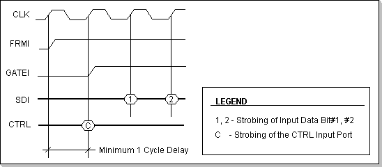
Figure 2: Timing for the Beginning of a Frame
The beginning of each new frame has to be signaled to the BCSI by
activating the FRMI input signal; this signal is assumed to be
externally synchronized with the CLK clock.
The first CLK rising edge within the frame is used by the BCSI to
strobe the CTRL port, and thus set up the cipher operation mode for the
whole period of the frame (the point marked "C" in Fig. 2). Thus, all
cipher control signals that are provided via the CTRL port (KEY, IV,
Mode, etc...) have to be valid at this time at the beginning of each
frame; during the rest of the frame the CTRL port is ignored (it's not
sampled).
A data bit within a frame is strobbed on the rising edge of each CLK
cycle, provided the GATEI signal is active at that moment. The GATEI
signal is assumed to be externally synchronized with the CLK clock. The
minimum delay required between the FRMI activation and GATEI's first
activation within a frame is one clock cycle (Fig. 2).
The Idle Input Cycles
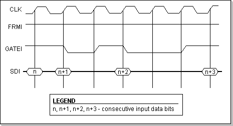
Figure 3: Timing for Idle Input Cycles
The idling input cycles are the ones in which no data is input in the BCSI (however, data might be output by the BCSI during idling input cycles). The rising edges of the CLK signal during which the GATEI signal is inactive will not strobe an input data bit (see Fig. 3). Input idle cycles can be inserted anywhere inside a frame, but they are NOT allowed to end a frame. Multiple consecutive idle cycles can be grouped together without restrictions. The GATEI is assumed to be externally synchronized with the CLK clock.
The Ending of a Frame
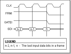
Figure 4: Timing for the End-of-Frame Sequence
The ending of a frame has to be signaled to the BCSI by inactivating the FRMI signal together with GATEI, right after the last data bit in the frame has been input; i.e. the next CLK rising edge after the last data bit in a frame must find both FRMI and GATEI inactive (see Fig. 4). No dummy cycles are allowed at this point, i.e. idle input cycles cannot end a frame. A frame must contain a multiple-of-K number of bits, where K is a customizable BCSI parameter; for example, if the input data is known to be byte-packed, K=8.
Inter-Frame Delay
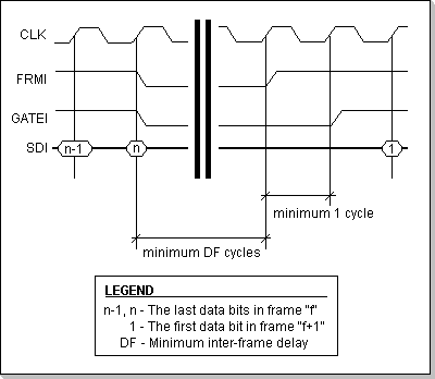
Figure 5: Timing for the inter-frame interval
The minimum delay between two consecutive frames depends on the processing time required by the cipher to perform an encryption/decryption operation (see Fig. 5). DF is a customizable BCSI parameter.
Output Signals Timing
The FRMO, GATEO, and SDO output signals are generated by the BCSI such
that they comply to their corresponding input signals timing
restrictions: the delay between frames is guaranteed to be at least DF
cycles, the delay between FRMO activation and the first GATEO
activation within a frame is one cycle, and the FRMO deactivation
occurs simultaneously with the GATEO deactivation, right after the last
bit in a frame has been output on the SDO line.
Neither FRMO nor GATEO are direct (delayed) replicates of their
corresponding inputs; their timing is a complex function of the input
data frame structure and the state of the BCSI at the beginning of the
frame.
However, some remarks can be made with respect to these two signals'
timing (hereafter W designates the width of the underlying
block-cipher):
- The FRMO signal activation occurs after minimum (DF)+(W/DF) cycles and maximum (DF+4)+W*(W/DF) cycles following the moment when a data block has been assembled by the BCSI from the input data stream; a block is assembled by the BCSI when either W bits have been input, or when the end-of-frame has been detected. This implies that FRMO can remain inactive indefinitely after a FRMI activation, until a data block can be assembled from the input, and thus there is no guaranteed maximum delay between FRMI and FRMO,
- The FRMO deactivation is affected by the time required for the cipher to process the last data block in a frame, and the internal FIFO buffers condition; it occurs after minimum (DF)+(W/DF) cycles and maximum (DF+4)+W*(W/DF+1) cycles following the FRMI deactivation,
- The GATEO signal is active within a frame in periods of W contiguous cycles, except the end-of-frame situations; periods of contiguous GATEO-inactive idle cycles may be inserted between the active periods. This behavior results from the BCSI having to serialize W-bit wide data blocks delivered by the underlying cipher, except the end-of-frame blocks that are shorter than W bits.